
Setting up a DVOM for different measurements
Note that results from the DVOM simulator may vary from actual workshop measurements, e.g. bulb resistance will vary with temperature. Please review the results with your supervisor.
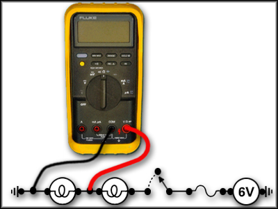
Voltage Measurement
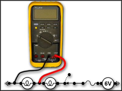
- Turn the circuit power on
- Insert the black lead into the COM plug and the red lead into the VΩ plug
- Turn the rotary dial to the DC Volt position
- Place the leads on either side of the component to be tested to measure voltage drop
Current Measurement

- Insert the red lead into the A port and the black lead into the COM port
- Turn the dial to the mA/A position
- Place both the meter leads onto the same point in the circuit. This will break the circuit and create a circuit that flows through the meter
- Apply power to the circuit
Caution: To prevent meter damage or blown fuses, check the installation thoroughly before applying any power. When measuring amperage, all the current in the circuit will flow through the meter.
Caution: Never place leads across a component when measuring amperage
When measuring circuit current, always begin with the red lead in the larger amperage input terminal. The lead should be moved to the smaller input (mA) only after it is determined that the current flow is below the maximum rating for that terminal.
Resistance Measurement
- Power must be off
- Insert the black lead in the COM port and the red lead in the VΩ port
- Turn the dial to the Ω position
- Place the leads across the component
Note: When measuring resistance, it is important to make sure the power is off. If the power is on, it will result in false readings.