Page 57 - CDX Heavy Vehicle Level 3 Chapter 6
P. 57
LEVEL 3 CHAPTER 6 Assessing and Repairing Heavy Duty Vehicle (HDV) Brake Systems and Components and Diagnosing Fault 229
This signal is read by the EBCM to determine the speed reluctance type is simpler and usually less expensive for
of each wheel, as well as the rate of deceleration of manufacturers to use. This style is sometimes called a
each wheel. This information is used to determine if a passive system since it is self-contained and needs no
wheel is starting to lock up and skid. A wheel sensor outside power to function. Magnetic induction occurs
assembly consists of a toothed tone wheel (or tone ring) when the teeth on the tone wheel pass the sensor, creat-
that rotates with the wheels and a stationary pick-up ing an analogue AC voltage signal. The faster the tone
assembly attached to the hub or axle housing. The pick- wheel rotates, the faster the AC signal frequency. This
up assembly and tone wheel do not touch each other; AC signal is sent to the ECU where it is processed and
a small gap, called an air gap, must be maintained at then compared to the AC signals from the other wheels.
the specified clearance. Since there is no mechanical Most variable reluctance wheel speed sensors are
connection, there is virtually no wear unless a foreign two-wire sensors, which complete the circuit back to
object gets between them. As each tooth of the tone the ECU. The variable reluctance sensor assembly con-
wheel approaches the pick-up, a small voltage is cre- sists of a coil of wire around a permanent magnet, with
ated that pushes current flow in one direction inside each end of the coil connected to one of the wheel
the pick-up assembly. As each tooth leaves the pick- speed sensor terminals, which connect directly into the
up assembly, voltage is generated that pushes current EBCM. Since this type of sensor operates on principles
flow in the opposite direction. This process creates a of magnetism, the air gap between the toothed tone
full-cycle sine wave for each tooth on the tone wheel
wheel and sensor is critical. If the air gap is too small,
. The faster the wheel is turned, the faster the parts could contact each other, damaging them. If FIGURE 6-10
the sine wave rises and falls. The speed at which the the air gap is too large, the sensor output signal to the
sine wave rises and falls is referred to as frequency. ECU could be too weak and trigger a code or cause the
Frequency is measured in hertz, where one hertz equals sensor to work intermittently.
one full-cycle sine wave per second.
One drawback to the variable reluctance sensor is that
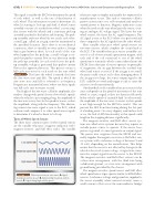
The height of the sine wave, called its amplitude, also since it depends on the speed of movement of the tone
tends to change with speed. At very slow vehicle speeds, wheel to create a signal, it does not function effectively
when the vehicle is just creeping along, the amplitude of below vehicle speeds of around 8 kph. In other words,
the sine wave is very low. As the speed increases, so does the amplitude of the sine wave it creates at slow speeds
the amplitude, along with the frequency. This alternat- is not high enough for the EBCM to read it. This can
ing current sine wave signal is sent to the ECU, which prevent the ABS from functioning during the last part
evaluates and compares it to other speed sensor signals of a braking event. On a very slippery road surface such
to determine if a wheel is about to lock up.
as ice, the lack of ABS functionality at that speed could
Types of Wheel Speed Sensors
lengthen the stopping distance significantly.
The magneto-resistive and Hall effect sensor sys-
The three most common types of wheel speed sensors
tems are called active systems because they require an
are the variable reluctance (magnetic induction style),
outside power source to operate. If the sensor loses
magneto-resistive, and Hall effect styles. The variable
power or ground, it cannot generate an output signal.
The power wire originates from the EBCM and nor-
mally supplies the magneto-resistive or Hall effect sen-
sor systems with a reference voltage of between 5 and
Low speed (A)
12 volts, depending on the manufacturer. This helps
ensure that the sensor is not affected by changes in the
vehicle’s electrical system voltage. A signal wire trans-
Moderate speed (B)
mits the output signal from the sensor to the EBCM.
The magneto-resistive and Hall effect sensors can be
a three-wire arrangement, with the third wire being
High speed (C)
a dedicated ground, or a two-wire arrangement with
ground being provided by the chassis.
The magneto-resistive speed sensor and Hall effect
wheel speed sensor types operate similar to all Hall effect
FIGURE 6-10
Wheel speed sensor sine wave. A. Signal
sensors. A reference voltage and ground are supplied to during low vehicle speed. B. Signal during moderate vehicle
the sensor assembly, where internal circuitry causes a speed. C. Signal during high vehicle speed.
small current to flow across the semiconductor bridge/