Page 9 - CDX Heavy Vehicle Level 3 Chapter 6
P. 9
LEVEL 3 CHAPTER 6 Assessing and Repairing Heavy Duty Vehicle (HDV) Brake Systems and Components and Diagnosing Fault 181
PROCEDURE
6-4
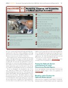
Removing, Cleaning and Inspecting
a Calliper and Pad Assembly
5 Remove about 2/3 of the brake fluid from the master
cylinder.
6 Raise the vehicle and support with safety stands.
7 Remove tyre and wheel assembly.
8 Pry calliper to one side.
9 Remove brake calliper retainer bolts.
10 Pull calliper assembly from rotor.
11 Use a C-clamp to compress the pistons. Watch for
possible brake fluid overflow at the reservoir during
this step. Caution: Do not let the front brake calliper
hang from the brake hose.
12 Remove brake pads from calliper.
Inspect calliper pistons for leaks. Note: If leaks are
13 1 Locate and follow the appropriate procedure in the
found, the brake calliper will need overhauling. Refer service manual.
to the brake calliper overhaul procedure in the service
manual.
2 Complete the accompanying job sheet or work order
with all pertinent information.
14 Inspect pads for wear and cracks.
3 Apply the parking brake.
15 List the test results and/or recommendations on the
job sheet or work order and clean work area and 4 Block the vehicle wheels.
return tools and materials to proper storage.
hubless rotors is generally easier than removing hub-style the rotor continuously hitting the brake pad while driv-
rotors, although some manufacturers design their rotors ing down the road. This constant rubbing on the high
to unbolt from the rear side of the bearing hub. In these spot of the rotor will wear it slightly, leading to excessive
applications, the wheel bearing hub must be removed thickness variation across the face of the rotor.
before the rotor can be removed from the hub.
Removing the rotor is usually required when the rotor
To inspect, measure, remove and reinstall a rotor needs to be replaced because it is under the specified
assembly, follow the guidelines in PROCEDURE 6-5 .
minimum thickness or would be after machining. It also
would need to be removed to be refinished on an off-car
Testing the Hydraulic System brake lathe or to service the wheel bearings or axle shaft.
Also, hubless rotors that are being machined with an on-
and Inspecting for Leaks;
vehicle brake lathe need to be removed to clean off the
Determining Needed Repairs
rust and dirt accumulated between the rotor and the hub.
To test the hydraulic system and inspect for leaks and Rotors are designed to be mounted in one of two
determine needed repairs, follow the guidelines in
ways: hub style or hubless style. The hub style has the
PROCEDURE 6-6 . wheel bearing hub cast into the rotor. This style generally
requires disassembly of the wheel bearing hub to remove
Bleeding and/or Flushing the
the rotor from the vehicle. The hubless style uses a wheel
bearing hub separate from the rotor, with the rotor held
Hydraulic Brake System
onto the hub by the wheel studs and lug nuts. Some hubs
When pressure is applied to brake fluid in a hydraulic also use small screws to hold the rotor on the hub when-
ever the wheel is removed from the vehicle. Removing
braking system, the brake fluid cannot be compressed